Skip to Content.
Sympa Menu

sphenix-magnet-l - [Sphenix-magnet-l] power consumption estimation in water-cooled-bus ... and delta-T

sphenix-magnet-l AT lists.bnl.gov

Subject: sPHENIX discussion of the superconducting solenoid

List archive

Chronological Thread  
  • From: "Yip, Kin" <kinyip AT bnl.gov>
  • To: "Streckenbach, Brian" <bstreckenbach AT bnl.gov>, "sphenix-magnet-l AT lists.bnl.gov" <sphenix-magnet-l AT lists.bnl.gov>
  • Subject: [Sphenix-magnet-l] power consumption estimation in water-cooled-bus ... and delta-T
  • Date: Wed, 30 Sep 2020 18:18:45 +0000

Hi,


This is a follow-up to the previous email and I change the subject to represent the subject a bit better.


(1)

  • Water-cooled-bus ... Say, let's call the resistance 3.4 µΩ / ft. (near the higher end of Dave's range).
  • R(100 ft) => 0.00034 Ohm ( for each sign)
  • Power = I^2 * R where I ~ 4600 A
  •       ~ 7.194 kW ... close to Dave's 7.2 kW (each).

While chatting with Carl, he made me remember that the nature of using 2 WCB’s (sharing 4600 A) per sign (+/-)  made the above estimation a factor of 2 wrong.


So, if I use the above assumption of 100 ft, each WCB is 0.00034 Ohm but each has only 4600/2 ~ 2300 A

  • total power = 2 * 0.00034 * 2300^2 ~  3.5972 kW, half of the above.


Nevertheless, 100 ft is probably an underestimate of the total WCB length;  but it should be  <200 ft (last time Brian estimated when we bought cables).  Brian is going to measure it again.

If we use 200 ft,  resistance is 6.8E-4 Ohm (for each WCB), total power = 7.194 kW again 😊


{ I guess Dave probably just used the 200 ft. }


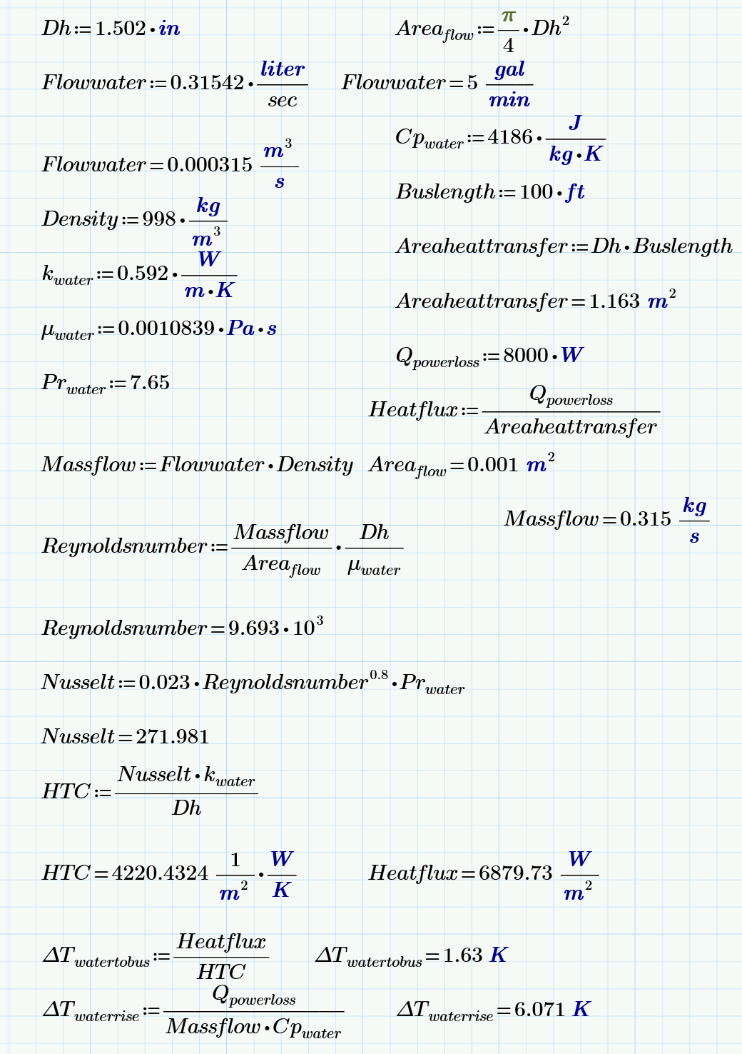
Roberto Than talked to me about the temperature gradient in the WCB (between the inner diameter of the bus and the water flow).  He made an estimation of the delta-T which I enclose below.


***************************************************** Roberto ******************************************************

Water flow

Water temperature and Heat transfer gradient between water and water cooled bus sets the final operating temperature of the power bus.

The final operating temperature sets the electrical resistance of bus, and thus the final Joule losses power dissipation.

Not too bad as expected.


**************************************************************************************************************************************************


Kin


From: sPHENIX-magnet-l <sphenix-magnet-l-bounces AT lists.bnl.gov> On Behalf Of Yip, Kin
Sent: Tuesday, September 29, 2020 5:00 PM
To: Streckenbach, Brian <bstreckenbach AT bnl.gov>; sphenix-magnet-l AT lists.bnl.gov
Subject: Re: [Sphenix-magnet-l] Can you give something for Carl Schultheiss to review ?


Hi,

Bob Lambiase gave me some ideas ... Modifying those ideas a bit,  I plug in some nos. and apply them to various Ohm's laws:


(1) Water-cooled-bus ... Say, let's call the resistance 3.4 µΩ / ft. (near the higher end of Dave's range).

R(100 ft) => 0.00034 Ohm ( for each sign)

Power = I^2 * R where I ~ 4600 A

      ~ 7.194 kW ... close to Dave's 7.2 kW (each).

{ We probably shouldn't count the distance in the air between 1008B and 1008 ...as mother nature takes of those ?!}


(2) Say, our total resistance is like BaBar's ~1.25E-3 Ohm.

Static Voltage across the dump resistor:  V = 4600 A * 1.25E-3 Ohm ~ 5.75 V

[ When it quenches, it's much larger .. but quench only last 38 sec < a minute ...]


Power in dump resistor (0.068 Ohm) ~ V^2/0.068 ~ 486 W  close to Dave's 0.5 kW.


(3) Power Supply, this one we have to check with Pablo.  There are 2 SCR's ?

If each one is 1 V, total power (for two) = 2*1V*4600A ~ 9.2 kW, just a bit bigger than Dave's 8 kW.


I wrote this

Kin

On 9/29/20 3:57 PM, Streckenbach, Brian wrote:

Carl/ Pablo,

I know this may take some time, but are these numbers something that you guys could corroborate? (doesn’t have to be right now)

I’m just trying to piece together daves puzzle pieces.

Thanks

Brian


From: Streckenbach, Brian
Sent: Friday, September 25, 2020 10:04 AM
To: Yip, Kin <kinyip AT bnl.gov>; Schultheiss, Carl <carls AT bnl.gov>
Cc: Rosas, Pablo J <rosas AT bnl.gov>
Subject: RE: Can you give something for Carl Schultheiss to review ?


Took daves email off this thread,

Yeah that is what I have

What I don’t have is how he got to those numbers

I’m assuming hes thinking all heat generated goes into the bus.

I just want you guys to look at those numbers as they pertain to 1008B and the systems youre responsible for.

Then I’d have more confidence in the cooling demand

Thanks

Brian


From: Yip, Kin <kinyip AT bnl.gov>
Sent: Friday, September 25, 2020 10:01 AM
To: Streckenbach, Brian <bstreckenbach AT bnl.gov>; 'Phillips, David B' <phillips AT bnl.gov>; Schultheiss, Carl <carls AT bnl.gov>
Cc: Rosas, Pablo J <rosas AT bnl.gov>
Subject: RE: Can you give something for Carl Schultheiss to review ?


Hi,


I’ve found David’s spreadsheet from the “EPS” area (that he’s left behind) and I attach it.  But it may not be that helpful.

I hope Carl and Pablo can comment ??


Kin


From: Streckenbach, Brian <bstreckenbach AT bnl.gov>
Sent: Friday, September 25, 2020 9:27 AM
To: 'Phillips, David B' <phillips AT bnl.gov>; Schultheiss, Carl <carls AT bnl.gov>
Cc: Yip, Kin <kinyip AT bnl.gov>; Rosas, Pablo J <rosas AT bnl.gov>
Subject: RE: Can you give something for Carl Schultheiss to review ?


Morning Guys

Im looking back at old conversations about the water cooled bus (see below for bus dimensions and resistance values).

Dave has a heat load spread sheet for the water cooled bus, Magnet power supply, and dump resistor.


Those highlighted values are in KW of heat generated.

Can I get confirmation from you guys that this is correct?

I know you guys talked great lengths to the resistance value of the bus line for a quench event and ramp down, so I submitted again a work request to get the bus line 3d modeled in Arno’s group.  This design would have to agree with your numbers so I’ll try and get this design on paper soon.


I don’t necessarily doubt Daves engineering ability, but due to him leaving id like us to just buy into the numbers he left behind.


If you need any additional info to verify these numbers let me know

Thanks

Brian


From: Phillips, David B <phillips AT bnl.gov>
Sent: Thursday, December 5, 2019 11:44 AM
To: Schultheiss, Carl <carls AT bnl.gov>
Cc: Yip, Kin <kinyip AT bnl.gov>; Streckenbach, Brian <bstreckenbach AT bnl.gov>; Rosas, Pablo J <rosas AT bnl.gov>
Subject: RE: Can you give something for Carl Schultheiss to review ?


Bus is covered with pvc pipe (joints in pvc are sleeved). The only exposed copper is at the flags and they will have cover boxes.


From: Schultheiss, Carl <carls AT bnl.gov>
Sent: Thursday, December 05, 2019 11:39 AM
To: Phillips, David B <phillips AT bnl.gov>
Cc: Yip, Kin <kinyip AT bnl.gov>; Streckenbach, Brian <bstreckenbach AT bnl.gov>; Rosas, Pablo J <rosas AT bnl.gov>
Subject: RE: Can you give something for Carl Schultheiss to review ?


Hi,


   So all the busses are the same dimensions. That’s

good they will share the current “equally”.

Do the busses have any protection from the elements

when they are outside? There is 2.625” between the

surfaces of the positive and negative conductors, when

the magnet quenches there will be 512 V between these surfaces.

   Do you know the length of the water cooled bus?


Thanks

Carl


From: Phillips, David B <phillips AT bnl.gov>
Sent: Thursday, December 05, 2019 11:27 AM
To: Yip, Kin <kinyip AT bnl.gov>; Streckenbach, Brian <bstreckenbach AT bnl.gov>; Schultheiss, Carl <carls AT bnl.gov>; Rosas, Pablo J <rosas AT bnl.gov>
Subject: RE: Can you give something for Carl Schultheiss to review ?


The magnet will be fed with 2 pairs of water cooled bus (WCB).

The pairs are ~12” apart (closest conductor to conductor), they are ~20” center to center.

Each of the pairs will have one positive and one negative conductor.

The space between the positive and negative conductor in one pair is ~5” center to center.

The bus is 2” double extra strong:

OD = 2.375”

ID = 1.503”

Wall thickness = 0.436”

Area = 2.66 sq in

R at 25C = 3.189 Micro-Ohms/ft

R at 50C = 3.465 Micro-Ohms/ft


For the connections between the power supply & rump resistor, and dump resistor & WCB we will use 12 each 535mcm cables in parallel.

The connections between the WCB and magnet will be the same 535mcm or equivalent jumpers.


From: Yip, Kin <kinyip AT bnl.gov>
Sent: Thursday, December 05, 2019 10:21 AM
To: Phillips, David B <phillips AT bnl.gov>; Streckenbach, Brian <bstreckenbach AT bnl.gov>; Schultheiss, Carl <carls AT bnl.gov>
Subject: Can you give something for Carl Schultheiss to review ?


Hi Dave and Brian,

I can't find you in your offices ... Yesterday, you guys told me that the cooling water design has been done on paper but just not on windshield (etc.).

I mentioned this to Carl and he asked whether you guys can give him/us something to review ?  He's hoping that you won't
have two different busses on the same direction ?

Can you please help ?  

Kin


Archive powered by MHonArc 2.6.24.

Top of Page